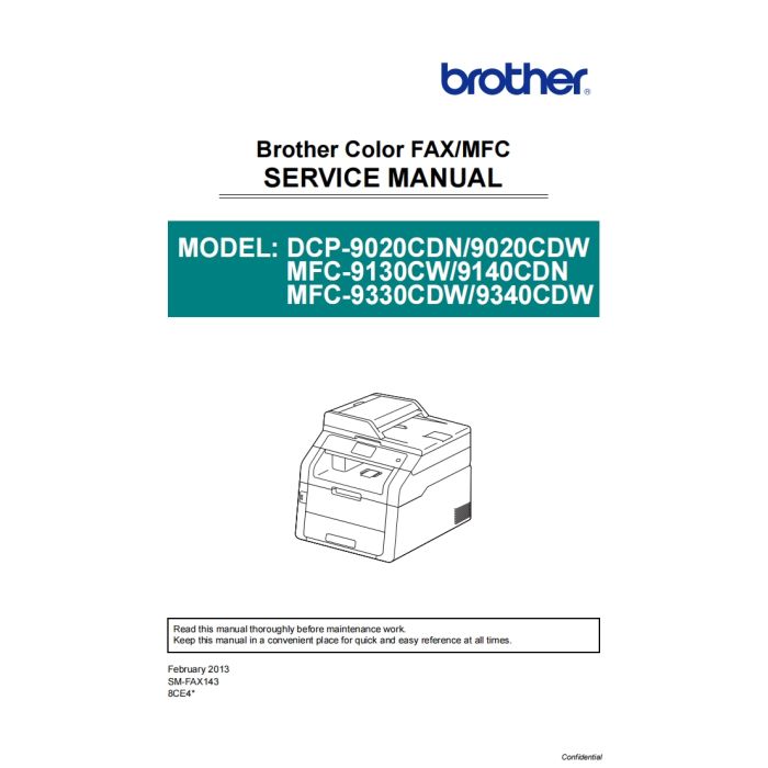
Brother Inkjet-MFC 9130CW 9140DN 9330CDW 9340CDW Inkjet-DCP 9020CDN 9020CDW Service Manual
$9.95
In stock
SKU
BR-9130-SM
- Download immediately after payment
- PDF format service manual
- Allow high-definition printing
CONTENTS
REGULATION................................................................................... I
SAFETY INFORMATION .................................................................V
CHAPTER 1 SPECIFICATIONS
1. SPECIFICATIONS LIST .............................................................................1-1
1.1 General....................................................................................................................... 1-1
1.2 Network Connectivity.................................................................................................. 1-7
1.3 Service Information..................................................................................................... 1-9
1.4 Supplies.................................................................................................................... 1-10
1.5 Paper ........................................................................................................................ 1-11
1.5.1 Paper handling ................................................................................................ 1-11
1.5.2 Media specifications ........................................................................................ 1-11
1.5.3 Type and size of paper .................................................................................... 1-11
1.6 Printable & Scannable Area...................................................................................... 1-12
1.7 Telephone ................................................................................................................. 1-12
1.8 FAX (Only for the models with FAX function) ........................................................... 1-13
1.9 Copy ......................................................................................................................... 1-13
1.10 Scanner .................................................................................................................. 1-14
1.11 USB Direct Interface ............................................................................................... 1-15
CHAPTER 2 ERROR INDICATION AND TROUBLESHOOTING
1. INTRODUCTION ........................................................................................2-1
1.1 Precautions................................................................................................................. 2-1
1.2 Initial Check ................................................................................................................ 2-3
2. OVERVIEW.................................................................................................2-5
2.1 Cross-section Drawing ............................................................................................... 2-5
2.1.1 Printer part......................................................................................................... 2-5
2.1.2 ADF unit/Document scanner unit....................................................................... 2-6
2.2 Paper Feeding ............................................................................................................ 2-7
2.2.1 Printer part......................................................................................................... 2-7
2.2.2 Scanning part .................................................................................................... 2-8
2.3 Operation of Each Part ............................................................................................... 2-9
2.4 Block Diagram .......................................................................................................... 2-10
2.5 Components ............................................................................................................. 2-11
3. ERROR INDICATIONS.............................................................................2-12
3.1 Error Codes .............................................................................................................. 2-12
3.2 Error Message .......................................................................................................... 2-24
3.3 Communications Error Code .................................................................................... 2-30
4. TROUBLESHOOTING .............................................................................2-34
4.1 Error Cause and Remedy......................................................................................... 2-34
4.2 Paper Feeding Problems.......................................................................................... 2-82
4.2.1 No paper feeding from paper tray.................................................................... 2-82
4.2.2 No paper feeding from the manual feed slot ................................................... 2-83
4.2.3 Double feeding ................................................................................................ 2-83
4.2.4 Wrinkles on paper............................................................................................ 2-84
4.2.5 Paper inclines diagonally................................................................................. 2-84
4.2.6 Curl of paper.................................................................................................... 2-85
4.2.7 Unable to perform 2-sided printing .................................................................. 2-85
4.2.8 Paper jam ........................................................................................................ 2-86
4.3 Image Defect Troubleshooting.................................................................................. 2-88
4.3.1 Image defect examples ................................................................................... 2-88
4.3.2 Troubleshooting image defect ......................................................................... 2-89
4.4 Software Setting Problems ..................................................................................... 2-103
4.4.1 Cannot print data ........................................................................................... 2-103
4.5 Network Problems .................................................................................................. 2-104
4.5.1 Cannot make a print through network connection ......................................... 2-104
4.6 Troubleshooting of the Control Panel ..................................................................... 2-105
4.6.1 Nothing is displayed on the LCD. .................................................................. 2-105
4.6.2 Unable to perform panel operation ................................................................ 2-105
4.6.3 Lamp malfunction .......................................................................................... 2-105
4.6.4 The touch panel does not work ..................................................................... 2-106
4.7 Troubleshooting of the Toner Cartridge and Drum Unit .......................................... 2-107
4.7.1 New toner not detected ................................................................................. 2-107
4.7.2 Cartridge error (Toner cartridge not detected) ............................................... 2-107
4.7.3 Toner low
(Even though a new toner cartridge is set, Toner low warning remains) ....... 2-107
4.7.4 Drum error ..................................................................................................... 2-108
4.7.5 Drum unit replacement
(Even though drum counter is reset, "Replace Drum" warning remains.)...... 2-108
4.8 Troubleshooting of the Fuser Unit .......................................................................... 2-109
4.8.1 Fuser unit failure............................................................................................ 2-109
4.9 Troubleshooting of the LED ASSY ......................................................................... 2-110
4.9.1 LED ASSY failure .......................................................................................... 2-110
4.10 Troubleshooting on the PCB..................................................................................2-111
4.10.1 Main PCB failure...........................................................................................2-111
4.10.2 Full memory..................................................................................................2-111
4.10.3 Print overrun .................................................................................................2-111
4.10.4 High-voltage power supply PCB failure ........................................................2-111
4.10.5 Low-voltage power supply PCB failure........................................................ 2-112
4.10.6 Modem PCB failure ..................................................................................... 2-112
4.11 Document Feeding Problems ............................................................................... 2-113
4.11.1 No feeding ................................................................................................... 2-113
4.11.2 Double feeding............................................................................................. 2-113
4.11.3 Paper jam .................................................................................................... 2-114
4.11.4 Wrinkles ....................................................................................................... 2-115
4.11.5 Document size cannot be correctly detected............................................... 2-115
4.12 Scanning Image Defect Troubleshooting.............................................................. 2-116
4.12.1 Image defect examples ............................................................................... 2-116
4.12.2 Troubleshooting image defect ..................................................................... 2-116
4.13 Troubleshooting of FAX Functions........................................................................ 2-119
4.13.1 FAX can't send it.......................................................................................... 2-119
4.13.2 FAX cannot be received. ............................................................................. 2-119
4.13.3 No bell ring .................................................................................................. 2-119
4.13.4 A communication error occurs..................................................................... 2-120
4.14 Others Problems................................................................................................... 2-121
4.14.1 The machine is not turned ON..................................................................... 2-121
4.14.2 Main fan not rotate....................................................................................... 2-121
4.14.3 Main motor failure........................................................................................ 2-121
4.14.4 Joint cover ASSY open................................................................................ 2-122
4.14.5 Back cover open.......................................................................................... 2-122
4.14.6 Unusual noise generated from the machine................................................ 2-122
4.14.7 Memory related failure................................................................................. 2-123
4.14.8 Printing related failure.................................................................................. 2-123
4.14.9 The USB interface does not work................................................................ 2-123
CHAPTER 3 DISASSEMBLY AND ASSEMBLY
1. SAFETY PRECAUTIONS ..........................................................................3-1
2. PACKING....................................................................................................3-2
3. SCREW CATALOGUE ...............................................................................3-3
4. SCREW TORQUE LIST .............................................................................3-4
5. LUBRICATION ...........................................................................................3-6
6. HARNESS ROUTING.................................................................................3-9
7. DISASSEMBLY FLOW.............................................................................3-24
8. DISASSEMBLY PROCEDURE ................................................................3-26
8.1 Lift Gear 46/Gear Z23M10Z14M75/Gear Z19M10 ................................................... 3-27
8.2 Cord Hook ................................................................................................................ 3-28
8.3 Back Cover ASSY .................................................................................................... 3-29
8.4 Fuser Cover ASSY ................................................................................................... 3-31
8.5 Fuser Unit .................................................................................................................3-32
8.6 Registration Mark L PCB ASSY/Registration Mark R PCB ASSY............................ 3-35
8.7 Side Cover L............................................................................................................. 3-38
8.8 Side Cover R ............................................................................................................ 3-40
8.9 Manual Feed Slot Cover ASSY ................................................................................ 3-41
8.10 Support Flap ........................................................................................................... 3-42
8.11 Joint Cover Side L................................................................................................... 3-43
8.12 Pull Arm L/Pull Arm R/Pull Arm Spring ................................................................... 3-44
8.13 Flat Cable Holder Cover ......................................................................................... 3-45
8.14 Hinge ASSY L/ADF Unit ......................................................................................... 3-48
8.15 Hinge R/Hinge R Support ....................................................................................... 3-51
8.16 Flat Cable Holder ASSY ......................................................................................... 3-52
8.17 Hinge Arm R ........................................................................................................... 3-52
8.18 ADF Document Output Support Flap...................................................................... 3-53
8.19 ADF Document Support ......................................................................................... 3-53
8.20 ADF Cover ASSY ................................................................................................... 3-54
8.21 Gear Cover ............................................................................................................. 3-55
8.22 Document Separate Roller ASSY........................................................................... 3-56
8.23 ADF Separation Pad Spring/ADF Separation Pad Holder ASSY ........................... 3-58
8.24 Second Side CIS Unit/Second Side CIS Flat Cable ............................................... 3-59
8.25 Paper Stack Lever .................................................................................................. 3-67
8.26 ADF Cover/Document Detection Sensor PCB ASSY............................................. 3-69
8.27 First Side Document Scanning Position Sensor PCB ASSY/
Second Side Document Scanning Position Sensor PCB ASSY
(Duplex Scanning Models Only) ............................................................................. 3-70
8.28 Eject Film................................................................................................................3-71
8.29 Document Feed Roller ASSY1 ............................................................................... 3-74
8.30 ADF Motor .............................................................................................................. 3-75
8.31 Document Cover ASSY.......................................................................................... 3-78
8.32 Pull Arm Guide/Lock Claw...................................................................................... 3-78
8.33 Flat Cable Cover/Holder Hook/LED ASSY ............................................................. 3-79
8.34 Z Spring L ............................................................................................................... 3-87
8.35 Joint Cover ASSY................................................................................................... 3-88
8.36 Modem PCB ASSY/Modem Flat Cable .................................................................. 3-92
8.37 Paper Stack Lever .................................................................................................. 3-94
8.38 Joint Cover Side R/Speaker Unit ............................................................................ 3-95
8.39 Joint Cover Back .................................................................................................... 3-96
8.40 Control Panel ASSY/Document Scanner Unit ........................................................ 3-97
8.41 Panel Control PCB ASSY....................................................................................... 3-99
8.42 Touch Panel ASSY/LCD ....................................................................................... 3-102
8.43 First Side CIS Unit/First Side CIS Flat Cable ....................................................... 3-103
8.44 LED Control Flat Cable......................................................................................... 3-108
8.45 LED Flat Cable ..................................................................................................... 3-112
8.46 LED Control PCB ASSY....................................................................................... 3-116
8.47 Back Cover Lower ................................................................................................ 3-117
8.48 Duplex Tray (2-sided Printing Model Only)........................................................... 3-118
8.49 External Temperature/Humidity Sensor PCB ASSY............................................. 3-119
8.50 Wireless LAN Cap/Wireless LAN PCB ASSY ...................................................... 3-120
8.51 Main PCB ASSY................................................................................................... 3-122
8.52 Develop Release Clutch ....................................................................................... 3-123
8.53 Process Drive Unit................................................................................................ 3-128
8.54 Fuser Drive Gear Z25........................................................................................... 3-131
8.55 Registration Clutch ............................................................................................... 3-132
8.56 Paper Feed Clutch................................................................................................ 3-133
8.57 Main Drive Unit ..................................................................................................... 3-134
8.58 Roller Holder ASSY .............................................................................................. 3-138
8.59 USB Host Replay PCB ASSY/Inner Front Cover ................................................. 3-140
8.60 Paper Feed Unit ................................................................................................... 3-142
8.61 Paper Eject ASSY ................................................................................................ 3-143
8.62 Back Cover Upper ................................................................................................ 3-145
8.63 Exit Roller Bushing R/Eject Roller ASSY.............................................................. 3-146
8.64 Back Cover Sensor Harness ASSY...................................................................... 3-147
8.65 Eject Sensor PCB ASSY ...................................................................................... 3-148
8.66 High-voltage Power Supply PCB ASSY/HVPS Flat Cable ................................... 3-149
8.67 Main Fan............................................................................................................... 3-155
8.68 Develop Release Sensor PCB ASSY................................................................... 3-155
8.69 Low-voltage Power Supply PCB ASSY ................................................................ 3-156
CHAPTER 4 ADJUSTMENTS AND UPDATING OF SETTINGS,
REQUIRED AFTER PARTS REPLACEMENT
1. IF YOU REPLACE THE MAIN PCB ASSY................................................4-1
1.1 Installing the Firmware (Sub firmware, Panel firmware, Main Firmware) ................... 4-2
1.1.1 Checking firmware version ................................................................................ 4-2
1.1.2 Installing the firmware using USB flash memory
(USB direct interface model only) ...................................................................... 4-3
1.1.3 Installing the firmware using computer .............................................................. 4-4
1.2 Initialization of EEPROM of Main PCB ASSY (Function code 01) ............................. 4-5
1.3 Setting by Country (Function code 74) ....................................................................... 4-5
1.4 Setting the Serial Number (Function code 80) ........................................................... 4-5
1.5 Restore Machine Information (Function code 41) ...................................................... 4-6
1.6 Performing the Motor Reset (Function code 57) ........................................................ 4-6
1.7 Performing the Continuous Adjustments of Density and Registration Sensors
(Function code 73)...................................................................................................... 4-6
1.8 Acquisition of White Level Data (Function code 55)................................................... 4-6
1.9 Adjustment of Touch Panel (Function code 61).......................................................... 4-6
2. IF YOU REPLACE THE REGISTRATION MARK L PCB ASSY AND
REGISTRATION MARK R PCB ASSY......................................................4-7
2.1 Performing the Continuous Adjustments of Density and Registration Sensor
(Function code 73)...................................................................................................... 4-7
3. IF YOU REPLACE THE LOW-VOLTAGE POWER SUPPLY PCB ASSY 4-8
3.1 Reset of Irregular Power Supply Detection Counter................................................... 4-8
4. IF YOU REPLACE THE PROCESS DRIVE UNIT......................................4-9
4.1 Performing the Motor Reset (Function code 57) ........................................................ 4-9
5. IF YOU REPLACE THE LED ASSY OR JOINT COVER ASSY..............4-10
5.1 Performing the Continuous Adjustments of Density and Registration Sensor
(Function code 73).................................................................................................... 4-10
6. IF YOU REPLACE THE DOCUMENT SCANNER UNIT,
ADF UNIT OR CIS UNIT ..........................................................................4-11
6.1 Acquisition of White Level Data (Function code 55)................................................. 4-11
7. IF YOU REPLACE THE CONTROL PANEL ASSY OR
TOUCH PANEL ASSY..............................................................................4-12
Confidential7.1 Installing the Panel Firmware ................................................................................... 4-13
7.1.1 Checking firmware version .............................................................................. 4-13
7.1.2 Installing the firmware using USB flash memory
(USB direct interface model only) .................................................................... 4-13
7.1.3 Installing the firmware using computer ............................................................ 4-14
7.2 Adjustment of Touch Panel (Function code 61)........................................................ 4-14
7.3 Operation Check of LCD (Function code 12) ........................................................... 4-14
7.4 Operation Check of Control Panel Key (Function code 13)...................................... 4-14
8. IF YOU REPLACE THE FUSER UNIT/PF KIT 1......................................4-15
8.1 Counter Reset after Fuser Unit/PF Kit 1 Replacement (Function code 88).............. 4-15
CHAPTER 5 SERVICE FUNCTIONS
1. MAINTENANCE MODE..............................................................................5-1
1.1 How to Enter the Maintenance Mode ......................................................................... 5-1
1.2 How to Enter the End User-accessible Maintenance Mode ....................................... 5-2
1.3 List of Maintenance-mode Functions.......................................................................... 5-3
1.4 Detailed Description of Maintenance-mode Functions ............................................... 5-5
1.4.1 EEPROM parameter initialization (Function code 01, 91) ................................. 5-5
1.4.2 Printout of scanning compensation data (Function code 05)............................. 5-6
1.4.3 Placement of CIS unit in position for transportation (Function code 06).......... 5-11
1.4.4 ADF performance test (Function code 08) ...................................................... 5-11
1.4.5 Monochrome image quality test pattern (Function code 09)............................ 5-12
1.4.6 Worker switch (WSW) setting and printout (Function code 10, 11) ................. 5-13
1.4.7 Operational check of LCD (Function code 12) ................................................ 5-17
1.4.8 Operational check of control panel key (Function code 13)............................. 5-18
1.4.9 Software version check (Function code 25)..................................................... 5-19
1.4.10 Operational check of sensors (Function code 32) ......................................... 5-20
1.4.11 LAN connection status display (Function code 33)........................................ 5-22
1.4.12 Backup of machine information (Function code 41) ...................................... 5-23
1.4.13 PC print function setting (Function code 43) ................................................. 5-25
1.4.14 Changing return value of USB No./Switching Dither Pattern/
Switching of ON/OFF of DirectPrint Color mode-Improve Gray Color
Switching of timing to execute Auto Registration
Adjusting left-end print start position on second side in duplex printing
(2-sided printing model only) (Function code 45) .......................................... 5-29
1.4.15 Set country/language (Function code 52)...................................................... 5-32
1.4.16 Transfer of received fax data and log information (Function code 53) .......... 5-33
1.4.17 Fine adjustment of scan positions (Function code 54) .................................. 5-35
Confidential1.4.18 Acquisition of white level data and setting of CIS scanning area
(Function code 55)......................................................................................... 5-36
1.4.19 Motor reset (Function code 57) ..................................................................... 5-37
1.4.20 Adjustment of touch panel (Function code 61) .............................................. 5-38
1.4.21 Adjustment of color registration
(Adjustment of inter-color position alignment) (Function code 66) ................ 5-39
1.4.22 Print test (Function code 67) ......................................................................... 5-42
1.4.23 LED test pattern print (Function code 68)...................................................... 5-45
1.4.24 Frame pattern print (One-sided) (Function code 69) ..................................... 5-47
1.4.25 Frame pattern print (Two-sided) (Function code 70) ..................................... 5-48
1.4.26 Color test pattern (Function code 71) ............................................................ 5-49
1.4.27 Sensitivity adjustment of density sensor (Function code 72)......................... 5-52
1.4.28 Continuous adjustments of density and registration sensor
(Function code 73)......................................................................................... 5-53
1.4.29 Setting by country (Function code 74)........................................................... 5-54
1.4.30 Printout of maintenance information (Function code 77)............................... 5-56
1.4.31 Operational check of fans (Function code 78)............................................... 5-59
1.4.32 Display of device log information (Function code 80).................................... 5-60
1.4.33 Display of device error codes (Function code 82) ......................................... 5-65
1.4.34 Developing bias voltage correction (Function code 83)................................. 5-66
1.4.35 Sending of communication log information to telephone line
(Function code 87)......................................................................................... 5-67
1.4.36 Counter reset after fuser unit/PF kit 1 replacement (Function code 88)........ 5-68
1.4.37 Exit from the maintenance mode (Function code 99).................................... 5-68
2. OTHER SERVICE FUNCTIONS...............................................................5-69
2.1 Toner Manual Reset Function................................................................................... 5-69
2.2 Parts Life Reset Function (Drum unit/Belt unit) ........................................................ 5-70
2.3 Deletion of User Setting Information, etc.................................................................. 5-71
2.4 How to Recover from Errors of the Fuser Unit ......................................................... 5-72
2.5 Drum Cleaning.......................................................................................................... 5-73
2.6 Deep Sleep Function ................................................................................................ 5-74
2.7 ROM Version Display ............................................................................................... 5-75
2.8 Demo Print Function................................................................................................. 5-76
CHAPTER 6 WIRING DIAGRAM
1. WIRING DIAGRAM ....................................................................................6-1
ConfidentialCHAPTER 7 PERIODICAL MAINTENANCE
1. PRECAUTIONS..........................................................................................7-1
2. PERIODICAL REPLACEMENT PARTS ....................................................7-2
2.1 Procedures to Replace Periodical Replacement Parts............................................... 7-2
2.1.1 PF Kit 1.............................................................................................................. 7-3
APPENDIX 1 SERIAL NUMBERING SYSTEM
APPENDIX 2 DELETION OF USER SETTING INFORMATION, ETC.
APPENDIX 3 INSTALLING THE MAINTENANCE PRINTER DRIVER
| BRAND | EPSON |
|---|---|
| TYPES | Service_Manual |
| SIZE | 21.7M |
| PAGES | 422 |
| FORMAT | |
| LANGUAGE | English |
| QUALITY | High resolution |
| VERSION | 1 |
| DOCDATE | 2013-01-02 00:00:00 |
| APPLIESTO | Brother Inkjet-MFC 9130CW Brother Inkjet-MFC 9140DN Brother Inkjet-MFC 9330CDW Brother Inkjet-MFC 9340CDW Brother Inkjet-DCP 9020CDN Brother Inkjet-DCP 9020CDW |
Related Products
Check items to add to the cart or