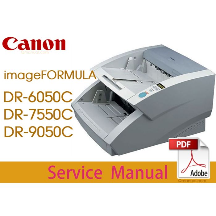
Canon imageFORMULA DR-6050C DR-7550C DR-9050C Service Manual and Parts List.
- Files without viruses
- PDF format service manual
- Allow high-definition printing
Canon imageFORMULA DR-6050C DR-7550C DR-9050C Service Manual and Parts List.pdf
Canon imageFORMULA DR-6050C
Canon imageFORMULA DR-7550C
Canon imageFORMULA DR-9050C
CHAPTER 1) GENERAL DESCRIPTION
I. PRODUCT SPECIFICATIONS
1. Features
2. Specifications
3. Precautions
II. NAME OF PARTS
1. Front Side
2. Rear Side
3. Control Panel
III. USER OPERATION
1. Preparation of Trays
2. Job Function
3. CapturePerfect 3.0
4. Paper Jam Handling
5. User Mode
CHAPTER 2) FUNCTIONS & OPERATION
I. OUTLINE
1. Basic Configuration
2. Roller Arrangement
3. Motor Drive
4. List of Sensors
5. Electrical Circuits
6. Timing Chart
II. READING SYSTEM
1. Outline
2. Image Reading
3. Shading
III. FEED SYSTEM
1. Outline
2. Pickup Tray Elevation
3. Separation Mechanism
4. Feed Error Detection
5. Staple Detection
IV. CONTROL SYSTEM
1. Control PCB
2. Drive System Block Diagram
3. Image Processing Control
V. POWER SUPPLY
1. Power Supply
VI. OPTION
1. Imprinter
2. Patchcode Decoder
3. Barcode Module
VII. ELECTRICAL PARTS LAYOUT
1. Motor, Fan, Solenoid
2. PCB, Sensor, Unit
VIII. PARTS LAYOUT ON EACH PCB
1. Control PCB
2. Main Drive PCB
3. Sub-Drive PCB
4. Power Supply PCB
5. Eject PCB
CHAPTER 3) DISASSEMBLY & REASSEMBLY
I. REPLACED BY USERS
1. Pickup Roller
2. Feed Roller
3. Retard Roller
II. EXTERNAL COVERS
1. Control PCB Cover
2. Right Cover
3. Operation Panel
4. Left Cover
5. Top Cover
6. Pickup Tray Unit
7. Eject Tray Unit
8. Upper Front Cover
9. Rear Cover
III. UPPER UNIT-1 (ELECTRICAL SYSTEM)
1. Main Drive PCB
2. Ultrasonic Sensor PCB
3. Feed Motor
4. Pickup Motor
5. Pickup Solenoid
IV. UPPER UNIT-2 (MECHANICAL SYSTEM)
1. Pickup Unit
2. Pickup Roller Cover
3. Upper Entrance Guide
4. Registration Roller Upper
5. Reading Roller Upper
6. Platen Roller Upper
7. Eject Roller (Follower)
8. U-Turn Roller (Follower)
9. Eject Tray Extension
10. Imprinter Cover
11. Eject Document Guide
12. Entire Upper Unit
V. UPPER UNIT-3 (READING SYSTEM)
1. Upper Reading Unit
2. Shading Motor
3. Upper Reading Glass Assembly
VI. BASE UNIT-1 (ELECTRICAL SYSTEM)
1. Control PCB
2. Sub-Drive PCB
3. Power Supply PCB
4. Ultrasonic Drive PCB
5. Eject PCB
6. Document Sensor PCB
7. Main Motor
8. Tray Motor
9. Separation Motor
10. Eject Motor
11. Exhaust Fan
VII. BASE UNIT-2 (MECHANICAL SYSTEM)
1. Pickup Document Guide
2. Tray Drive Box
3. Blind Cover
4. Lower Front Cover
5. Lower Entrance Guide
6. Belt (Right)
7. Belt (Left)
8. Registration Roller Lower
9. Platen Roller Lower
10. Reading Roller Lower
11. Drive U-turn Roller (Front)
12. Drive U-turn Roller (Middle)
13. Drive U-turn Roller (Rear)
14. Eject Drive Unit
15. Eject Roller (Drive)
VIII. BASE UNIT-3 (READING SYSETM)
1. Lower Reading Unit
2. Shading Motor
3. Lower Reading Glass Assembly
CHAPTER 4) INSTALLATION & MAINTENANCE
I. INSTALLATION
1. Choosing Location
2. Unpacking And Installation
3. Imprinter Installation Procedure
4. Patchcode Decoder Installation
Procedure
II. PARTS REPLACEMENT
1. Periodically Replaced Parts
2. Consumable Parts (Commercial Goods)
3. Consumable Parts (For User)
4. Consumable Parts (For servicing)
III. MAINTENANCE
1. User Maintenance
2. Service Maintenance
CHAPTER 5) TROUBLESHOOTING
I. ERROR DISPLAY
1. Main Body
2. Computer
II. SERVICE MODE
A. Outline
1. Outline
2. Installation Procedure
3. Starting Up and Exiting Service Mode
B. Main Menu
1. All Adjustment
2. Individual Adjustments
3. Max Document Size
4. Sleep
5. SCSI Transfer
6. Counter
C. Dcon Check
1. Motor
2. Feed Test
3. Sensors
4. LED/LCD
D. Get Status
1. Last Error Logs
2. Check Device
3. Serial Number
4. Write Setting to Text
E. Scan
1. Scan Check
2. CIS Data
3. ImgFrame
F. Extended Setting
1. Regist Manual Adjustment
2. Key Lock
G. Firmware Change
1. Firmware registration
2. Controller Firmware Loading
3. Drive Firmware Loading
H. Others
1. Imprinter
2. Patchcode
3. Analog Sensor
4. Application Information
5. Simulation Mode
III. LIST OF FAILURES
1. Operation Failures
2. Images Failures
IV. OPERATION TROUBLESHOOTING
1. No Power Is Supplied
2. Scanner Is Not Recognized
3. Scanning Does Not Start
4. Documents Are Not Fed Properly
5. Scanning Speed Is Slow
V. IMAGE TROUBLESHOOTING
1. Completely Black, Completely White,
All Streaks
2. Too Dark, Too Light
3. Black Borders Around Image
4. Image Skews
5. Streaks on Image
6. Moire on Image
7. Outer Areas of Image Disappear
8. Text Invisible
VI. AFTER REPLACING PARTS
APPENDIX
I. GENERAL DIAGRAM
| BRAND | CANON |
|---|---|
| TYPES | Service_Manual, Parts_Manual |
| SIZE | 105M |
| PAGES | 451 |
| FORMAT | |
| LANGUAGE | English |
| QUALITY | High resolution |
| VERSION | Edition 1 |
| DOCDATE | 2022-01-07 00:00:00 |
| APPLIESTO | Canon imageFORMULA DR-6050C Canon imageFORMULA DR-7550C Canon imageFORMULA DR-9050C |