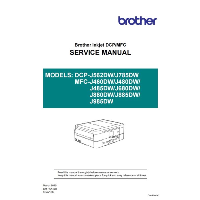
Brother Inkjet-MFC J460DW J480DW J485DW J680DW J880DW J885DW J985DW Inkjet-DCP J562DW J785DW Service Manual
$9.95
In stock
SKU
BR-J460-SM
- Download immediately after payment
- PDF format service manual
- Allow high-definition printing
TABLE OF CONTENTS
REGULATION......................................................................................................................... ix
SAFETY INFORMATION...................................................................................................... xiv
CHAPTER 1 SPECIFICATIONS......................................................................................... 1-1
1 GENERAL ...................................................................................................................... 1-1
1.1 General.................................................................................................................. 1-1
1.2 Media Specification ............................................................................................... 1-2
1.3 Paper Handling...................................................................................................... 1-3
1.4 LCD Panel ............................................................................................................. 1-3
1.5 Memory.................................................................................................................. 1-3
1.6 Interface................................................................................................................. 1-4
1.7 Others.................................................................................................................... 1-5
2 FAX................................................................................................................................. 1-5
3 PRINTER ........................................................................................................................ 1-6
4 COPY.............................................................................................................................. 1-6
5 SCANNER ...................................................................................................................... 1-7
6 SOFTWARE ................................................................................................................... 1-7
7 NETWORK ..................................................................................................................... 1-8
7.1 Network ................................................................................................................. 1-8
7.2 Wired ..................................................................................................................... 1-8
7.3 Wireless................................................................................................................. 1-8
8 SUPPLIES/OPTIONS..................................................................................................... 1-9
9 SERVICE INFORMATION.............................................................................................. 1-9
10 PAPER ......................................................................................................................... 1-10
10.1 Paper................................................................................................................... 1-10
10.2 Printable Area...................................................................................................... 1-12
CHAPTER 2 TROUBLESHOOTING................................................................................... 2-1
1 INTRODUCTION ............................................................................................................ 2-1
1.1 Precautions............................................................................................................ 2-1
1.2 Initial Check........................................................................................................... 2-2
2 OVERVIEW .................................................................................................................... 2-3
2.1 Cross-section Drawings......................................................................................... 2-3
ii
2.1.1 Document scanning ...................................................................................... 2-3
2.1.2 Printer part .................................................................................................... 2-3
2.2 Document Feeding/Recording Paper Feeding path .............................................. 2-4
2.2.1 Document feeding path................................................................................. 2-4
2.2.2 Recording paper feeding path....................................................................... 2-4
2.3 Function of Each Sensor/Roller............................................................................. 2-5
2.4 Block Diagram ....................................................................................................... 2-6
2.5 Components .......................................................................................................... 2-7
3 ERROR INDICATION..................................................................................................... 2-8
3.1 Error Codes ........................................................................................................... 2-8
3.2 Error Messages ................................................................................................... 2-12
3.3 Communications Error......................................................................................... 2-15
4 TROUBLESHOOTING ................................................................................................. 2-19
4.1 Error Cause and Solutions .................................................................................. 2-19
4.2 Recording Paper Feeding Problems ................................................................... 2-48
4.2.1 Recording paper is not fed from paper tray................................................. 2-48
4.2.2 Paper is not fed from manual feed slot ....................................................... 2-49
4.2.3 Two or more sheets of paper fed at a time ................................................. 2-49
4.2.4 Recording paper feeding at an angle.......................................................... 2-50
4.2.5 Recording paper is wrinkling....................................................................... 2-50
4.2.6 Recording paper jam................................................................................... 2-51
4.2.7 Cannot perform duplex printing................................................................... 2-55
4.3 Print-image Problems.......................................................................................... 2-56
4.3.1 Defective images......................................................................................... 2-56
4.3.2 Troubleshooting by print-image defect........................................................ 2-57
4.4 Software-related Problems.................................................................................. 2-68
4.4.1 Cannot print data......................................................................................... 2-68
4.5 Network Problems ............................................................................................... 2-68
4.5.1 Cannot print through a network connection ................................................ 2-68
4.6 Control Panel Problems....................................................................................... 2-69
4.6.1 No display on the LCD ................................................................................ 2-69
4.6.2 LED does not light up.................................................................................. 2-69
4.6.3 The control panel does not work................................................................. 2-69
4.6.4 Touch panel inoperative.............................................................................. 2-70
4.7 Document Feeding Problems.............................................................................. 2-71
4.7.1 Document cannot be fed............................................................................. 2-71
4.7.2 Document double feeding ........................................................................... 2-71
iii
4.7.3 Document jam............................................................................................. 2-72
4.7.4 Wrinkles on documents............................................................................... 2-75
4.7.5 Document size not correctly detected......................................................... 2-75
4.8 Scanned-image Problems ................................................................................... 2-76
4.8.1 Defective images......................................................................................... 2-76
4.8.2 Scanned-image Problems........................................................................... 2-76
4.9 Fax Problems ...................................................................................................... 2-80
4.9.1 Fax sending cannot be performed .............................................................. 2-80
4.9.2 Cannot receive fax ...................................................................................... 2-80
4.9.3 A communications error occurs................................................................... 2-80
4.10 Other Problems ................................................................................................... 2-81
4.10.1 The machine cannot be powered on........................................................... 2-81
4.10.2 Memory card/PictBridge does not function (no response) .......................... 2-81
4.10.3 Memory card/PictBridge data cannot be read............................................. 2-82
4.10.4 Internal memory errors................................................................................ 2-82
CHAPTER 3 DISASSEMBLY AND ASSEMBLY ............................................................... 3-1
1 PRECAUTIONS BEFORE PROCEEDING .................................................................... 3-1
2 PACKING .......................................................................................................................3-1
3 SCREW CATALOGUE................................................................................................... 3-2
4 SCREW TORQUE LIST ................................................................................................. 3-3
5 LUBRICATION ............................................................................................................... 3-4
6 OVERVIEW OF GEARS............................................................................................... 3-11
7 ROUTING OF HARNESSES, FLAT CABLE AND INK SUPPLY TUBES................... 3-12
8 DISASSEMBLY FLOW ................................................................................................ 3-21
9 DISASSEMBLY PROCEDURE.................................................................................... 3-22
9.1 Preparation.......................................................................................................... 3-22
9.2 Scanner Cover Damper/Scanner Cover Support ................................................ 3-26
9.3 Head/carriage Unit/CR Timing Belt ..................................................................... 3-27
9.4 Document Scanner Unit/ADF Unit (Models with ADF)/Document Cover ASSY
(Models without ADF).......................................................................................... 3-37
9.5 CIS Unit/CIS Flat Cable....................................................................................... 3-43
9.6 ADF Top Cover Front (For ADF Models Only) .................................................... 3-48
9.7 ADF Top Cover Rear (For ADF Models Only)..................................................... 3-49
9.8 ADF Document Support (For ADF Models Only) ................................................ 3-49
iv
9.9 ADF Cover ASSY (For ADF Models Only) .......................................................... 3-50
9.10 ADF Separation Pad Holder ASSY (For ADF Models Only) ............................... 3-50
9.11 Document Scanning Position Sensor PCB ASSY (For ADF Models Only)......... 3-51
9.12 Document Detection Sensor PCB ASSY (For ADF Models Only)....................... 3-52
9.13 ADF Top Cover Center (For ADF Models Only).................................................. 3-53
9.14 Document Separate Roller ASSY (For ADF Models Only).................................. 3-54
9.15 Ink Cartridge Cover ............................................................................................. 3-56
9.16 Control Panel ASSY ............................................................................................ 3-57
9.17 Front Cover.......................................................................................................... 3-59
9.18 Manual Feed Slot ................................................................................................ 3-60
9.19 Wireless LAN PCB ASSY.................................................................................... 3-60
9.20 Jam Clear Cover.................................................................................................. 3-61
9.21 Upper Cover ........................................................................................................ 3-62
9.22 Carriage PCB ASSY............................................................................................ 3-64
9.23 Ink Absorber Box................................................................................................. 3-65
9.24 Ink Refill ASSY .................................................................................................... 3-66
9.25 Ink Absorber Felt (For Ink Refill ASSY)............................................................... 3-67
9.26 Ink Cartridge Cover Sensor ASSY ...................................................................... 3-67
9.27 Main PCB ............................................................................................................ 3-68
9.28 Power Supply PCB ASSY ................................................................................... 3-72
9.29 Modem PCB ASSY.............................................................................................. 3-75
9.30 CR Encoder Strip................................................................................................. 3-76
9.31 Carriage Motor..................................................................................................... 3-77
9.32 Flushing Guide .................................................................................................... 3-78
9.33 Flushing Foam..................................................................................................... 3-78
9.34 PF Encoder Disk.................................................................................................. 3-79
9.35 Registration Sensor PCB ASSY.......................................................................... 3-79
9.36 Paper Feed Roller ............................................................................................... 3-81
9.37 Paper Feed Motor................................................................................................ 3-83
9.38 PF Encoder Sensor PCB ASSY .......................................................................... 3-83
9.39 Maintenance Unit................................................................................................. 3-84
9.40 Ink Absorber Felt (For Maintenance Unit) ........................................................... 3-84
9.41 Platen ASSY/Paper ejection roller....................................................................... 3-85
9.42 Switchback Roller ASSY ..................................................................................... 3-86
9.43 Paper Pull-in Roller.............................................................................................. 3-87
9.44 Bank ASSY.......................................................................................................... 3-88
9.45 Base Pad/Base Pad W........................................................................................ 3-89
v
CHAPTER 4 ADJUSTMENTS AND UPDATING OF SETTINGS, REQUIRED AFTER
PARTS REPLACEMENT............................................................................... 4-1
1 IF YOU REPLACE THE MAIN PCB ASSY.................................................................... 4-1
1.1 Customize destinations (Maintenance mode 74) .................................................. 4-3
1.2 Set the CIS type (Maintenance mode 59) ............................................................. 4-3
1.3 Install the firmware (Maintenance mode 28) ......................................................... 4-3
1.4 Initialize the EEPROM parameters (Maintenance mode 01)................................. 4-6
1.5 Restore the head Calibration data (Maintenance mode 68).................................. 4-6
1.6 Set the serial number (Maintenance mode 80) ..................................................... 4-6
1.7 Update the head property data (Maintenance mode 68)....................................... 4-7
1.8 Restore machine information (Maintenance mode 46).......................................... 4-7
1.9 Adjust the touch panel (Maintenance mode 78).................................................... 4-7
1.10 Acquire white/black level data (Maintenance mode 55) ........................................ 4-8
1.11 Adjustment of software correction for inclination/corrugation/ruled lines
(Maintenance mode 65)......................................................................................... 4-8
1.12 Update the paper feeding correction values (Maintenance mode 58)................... 4-8
1.13 Adjust margins in borderless printing (Maintenance mode 66) ............................. 4-8
1.14 Reset purge and flushing counts........................................................................... 4-8
1.15 Write head calibration data (Maintenance mode 02)............................................. 4-8
1.16 Check scanning and printing ................................................................................. 4-9
2 IF YOU REPLACE THE HEAD/CARRIAGE UNIT....................................................... 4-10
2.1 Update the head property data (Maintenance mode 68)..................................... 4-11
2.2 Perform ink supply purge (Maintenance mode 76).............................................. 4-12
2.3 Check head nozzles (Maintenance mode 09) ..................................................... 4-12
2.4 Adjust head inclination......................................................................................... 4-12
2.5 Adjustment of software correction for inclination/corrugation/ruled lines
(Maintenance mode 65)....................................................................................... 4-17
2.6 Update the paper feeding correction values (Maintenance mode 58)................. 4-17
2.7 Adjust margins in borderless printing (Maintenance mode 66) ........................... 4-17
2.8 Write head calibration data (Maintenance mode 02)........................................... 4-17
2.9 Check printing...................................................................................................... 4-17
2.10 Obtain machine information at the user site (Instruction to the end user)........... 4-17
3 IF YOU REPLACE THE DOCUMENT SCANNER UNIT, ADF UNIT OR CIS UNIT.... 4-19
3.1 Set the CIS type (Maintenance mode 59) (Not required after replacement of the
ADF unit) ............................................................................................................. 4-19
3.2 Acquire white/black level data (Maintenance mode 55) (Not required after
replacement of the ADF unit)............................................................................... 4-19
3.3 Check scanning................................................................................................... 4-19
vi
4 IF YOU REPLACE THE CONTROL PANEL ASSY, LCD, PANEL PCB ASSY,
TOUCH KEY PCB and RUBBER KEY........................................................................ 4-20
4.1 Adjust the touch panel (Maintenance mode 78).................................................. 4-20
4.2 Check LCD operation (Maintenance mode 12) ................................................... 4-20
4.3 Check the operation of the control panel keys (Maintenance mode 13) ............. 4-20
5 IF YOU REPLACE THE INK ABSORBER BOX OR FLUSHING FOAM .................... 4-20
5.1 Reset purge and flushing counts......................................................................... 4-20
6 IF YOU REPLACE THE RECORDING PAPER FEEDING PARTS, HEAD/
CARRIAGE PARTS and MAINTENANCE UNIT ......................................................... 4-21
6.1 Check head nozzles (Maintenance mode 09) ..................................................... 4-22
6.2 Adjustment of software correction for inclination/corrugation/ruled lines
(Maintenance mode 65)....................................................................................... 4-22
6.3 Update paper feeding correction values (Maintenance mode 58)....................... 4-22
6.4 Adjust margins in borderless printing (Maintenance mode 66) ........................... 4-22
6.5 Check printing...................................................................................................... 4-22
CHAPTER 5 SERVICE FUNCTIONS ................................................................................. 5-1
1 MAINTENANCE MODE ................................................................................................. 5-1
1.1 Entry to the Maintenance Mode............................................................................. 5-1
1.1.1 How to Enter the Maintenance Mode for Service Personnel ........................ 5-1
1.1.2 How to Enter the End User-accessible Maintenance Mode.......................... 5-3
1.2 List of Maintenance-mode Functions..................................................................... 5-5
1.3 Detailed Description of Maintenance-mode Functions.......................................... 5-6
1.3.1 EEPROM Parameter Initialization (Maintenance mode 01, 91) .................... 5-6
1.3.2 Creating of Head Calibration Data and Writing it into Flash ROM
(Maintenance mode 02) ................................................................................ 5-7
1.3.3 ADF Performance Test (Maintenance mode 08) ........................................ 5-10
1.3.4 Printout of Test Pattern (Maintenance mode 09) ........................................ 5-10
1.3.5 Worker Switch Setting and Printout (Maintenance modes 10 and 11)........ 5-11
1.3.6 Operational Check of LCD (Maintenance mode 12) ................................... 5-14
1.3.7 Operational Check of Keys on Control Panel (Maintenance mode 13)....... 5-17
1.3.8 EEPROM Dump and Log Information Saving (Maintenance mode 17)...... 5-18
1.3.9 Updating of Firmware Using an External Memory
(Maintenance mode 28) .............................................................................. 5-19
1.3.10 Sensor Operational Check (Maintenance mode 32) ................................... 5-20
1.3.11 Printout of Dial Log (Maintenance mode 37)............................................... 5-21
1.3.12 Backup of Machine Information (Maintenance mode 46)............................ 5-22
1.3.13 Setting of Country/Language (Maintenance mode 52) ............................... 5-24
vii
1.3.14 Transfer of Received FAX Data and/or Equipment's Log
(Maintenance mode 53) .............................................................................. 5-25
1.3.15 Fine Adjustment of Scanning Position (Maintenance mode 54) ................. 5-27
1.3.16 Acquisition of White/Black Level Data and CIS Scanner Area Setting
(Maintenance mode 55) .............................................................................. 5-28
1.3.17 Cartridge IC Communication Check (Maintenance mode 57)..................... 5-29
1.3.18 Updating of Paper Feeding Correction Values (Maintenance mode 58)..... 5-30
1.3.19 Checking of CIS Travel and Specifying of CIS Type
(Maintenance mode 59) .............................................................................. 5-34
1.3.20 Printout of PRN/JPEG Files in Memory Card (Maintenance mode 61)....... 5-35
1.3.21 Move of the Head/Carriage Unit to the Adjustment Position
(Maintenance mode 63) .............................................................................. 5-36
1.3.22 Adjustment of Software Correction for Inclination/Corrugation/Ruled Lines
(Maintenance mode 65) .............................................................................. 5-37
1.3.23 Margin Adjustment in Borderless Printing (Maintenance mode 66) ............ 5-39
1.3.24 Updating of Head Property Data and Backup/Restoration of Head
Calibration Data (Maintenance mode 68) ................................................... 5-42
1.3.25 Traveling Speed Check of Head/Carriage Unit (Maintenance mode 69) .... 5-44
1.3.26 Customizing Destinations (Maintenance mode 74)..................................... 5-45
1.3.27 Move of the Head/Carriage Unit to the Flushing Position
(Maintenance mode 75) .............................................................................. 5-47
1.3.28 Purge Operation (Maintenance mode 76)................................................... 5-48
1.3.29 Print of the Maintenance Information (Maintenance mode 77) ................... 5-53
1.3.30 Adjustment of Touch Panel (Maintenance mode 78) .................................. 5-56
1.3.31 Display of the Equipment's Log (Maintenance mode 80)............................ 5-57
1.3.32 Equipment Error Code Indication (Maintenance mode 82)......................... 5-61
1.3.33 Output of Transmission Log to the Telephone Line
(Maintenance mode 87) .............................................................................. 5-61
1.3.34 Assurance Mode Switch Setting (Maintenance mode 88) .......................... 5-62
2 OTHER SERVICE FUNCTIONS .................................................................................. 5-71
2.1 Displaying the Firmware Version......................................................................... 5-71
2.2 Moving the Head/Carriage Unit ........................................................................... 5-71
2.3 Retrieving the Equipment Log Information .......................................................... 5-72
CHAPTER 6 CIRCUIT DIAGRAMS AND WIRING DIAGRAMS ........................................ 6-1
CHAPTER 7 PERIODICAL MAINTENANCE ..................................................................... 7-1
1 PERIODICAL REPLACEMENT PARTS ........................................................................ 7-1
APPENDIX 1 SERIAL NUMBERING SYSTEM ........................................................ App. 1-1
viii
APPENDIX 2 DELETION OF USER SETTING INFORMATION .............................. App. 2-1
Deleting User Setting Info from the machine .......................................................... App. 2-1
APPENDIX 3 INSTALLING THE MAINTENANCE PRINTER DRIVER.................... App. 3-1
| BRAND | EPSON |
|---|---|
| TYPES | Service_Manual |
| SIZE | 31.7M |
| PAGES | 448 |
| FORMAT | |
| LANGUAGE | English |
| QUALITY | High resolution |
| VERSION | 3 |
| DOCDATE | 2015-01-03 00:00:00 |
| APPLIESTO | Brother Inkjet-MFC J460DW Brother Inkjet-MFC J480DW Brother Inkjet-MFC J485DW Brother Inkjet-MFC J680DW Brother Inkjet-MFC J880DW Brother Inkjet-MFC J885DW Brother Inkjet-MFC J985DW Brother Inkjet-DCP J562DW Brother Inkjet-DCP J785DW |


