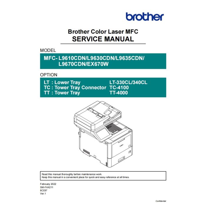
Brother Color-Laser-MFC L9610CDN L9630CDN L9635CDN L9670CDN EX670W Service Manual
$9.95
In stock
SKU
BR-L9610-SM
- Download immediately after payment
- PDF format service manual
- Allow high-definition printing
CONTENTS
SAFETY INFORMATION
GLOSSARY
CHAPTER 1 SUPPLEMENTAL SPECIFICATIONS
1. GENERAL ................................................................................................................. 1-1
2. FAX / COPY / SCANNER.......................................................................................... 1-2
3. SERVICE INFORMATION / SUPPLIES.................................................................... 1-3
4. DIMENSIONS / WEIGHT........................................................................................... 1-4
CHAPTER 2 ERROR INDICATION AND TROUBLESHOOTING
1. INTRODUCTION ....................................................................................................... 2-1
1.1 Precautions................................................................................................................................... 2-1
1.2 Checks before Commencing Troubleshooting.............................................................................. 2-2
1.2.1 Operating environment ........................................................................................................ 2-2
1.2.2 Power supply ....................................................................................................................... 2-2
1.2.3 Paper ................................................................................................................................... 2-2
1.2.4 Consumable parts................................................................................................................ 2-2
1.2.5 Others .................................................................................................................................. 2-2
1.2.6 Cleaning............................................................................................................................... 2-3
2. OVERVIEW ............................................................................................................... 2-4
2.1 Cross-section Drawing.................................................................................................................. 2-4
2.1.1 Printer part ........................................................................................................................... 2-4
2.1.2 LT......................................................................................................................................... 2-5
2.1.3 TT......................................................................................................................................... 2-6
2.1.4 ADF...................................................................................................................................... 2-7
2.2 Paper Feeding .............................................................................................................................. 2-8
2.2.1 Printer part ........................................................................................................................... 2-8
2.2.2 LT......................................................................................................................................... 2-9
2.2.3 TT....................................................................................................................................... 2-10
2.2.4 ADF.....................................................................................................................................2-11
2.3 Operation of Each Part and Location of Parts ............................................................................ 2-12
2.4 Block Diagram............................................................................................................................. 2-17
2.5 Main Components....................................................................................................................... 2-19
Confidential3. ERROR INDICATIONS............................................................................................ 2-21
3.1 Error Codes ................................................................................................................................ 2-21
3.2 Error Messages........................................................................................................................... 2-27
3.3 Communication Error Codes....................................................................................................... 2-39
4. TROUBLESHOOTING ............................................................................................ 2-42
4.1 Error Cause and Remedy ........................................................................................................... 2-42
4.2 Troubleshooting for Paper Feeding Problems .......................................................................... 2-106
4.2.1 No paper feeding from T1................................................................................................ 2-106
4.2.2 No paper feeding from LT ................................................................................................ 2-107
4.2.3 No paper feeding from TT................................................................................................ 2-108
4.2.4 No paper feeding from MP tray........................................................................................ 2-109
4.2.5 Multiple sheets of paper are fed....................................................................................... 2-109
4.2.6 Paper becomes wrinkled...................................................................................................2-110
4.2.7 Paper is fed at an angle....................................................................................................2-110
4.2.8 Paper curls........................................................................................................................2-110
4.2.9 Unable to perform 2-sided printing....................................................................................2-111
4.2.10 Paper jam........................................................................................................................2-112
4.3 Troubleshooting for Image Defects............................................................................................2-113
4.3.1 Image defect examples.....................................................................................................2-113
4.3.2 Troubleshooting for each image defect.............................................................................2-114
4.4 Troubleshooting for Software Problems.................................................................................... 2-129
4.4.1 Does not receive data...................................................................................................... 2-129
4.5 Troubleshooting for Network Problems..................................................................................... 2-130
4.5.1 Cannot make a print through network connection ........................................................... 2-130
4.5.2 Cannot connect to access point....................................................................................... 2-130
4.6 Troubleshooting for Control Panel ............................................................................................ 2-131
4.6.1 Nothing is displayed on the LCD...................................................................................... 2-131
4.6.2 No LED indication ............................................................................................................ 2-131
4.6.3 Unable to perform panel operation .................................................................................. 2-131
4.7 Troubleshooting for Toner Cartridge and Drum Unit ................................................................. 2-132
4.7.1 Toner cartridge not detected ............................................................................................ 2-132
4.7.2 Error message prompting toner cartridge replacement does not disappear.................... 2-132
4.7.3 Drum error........................................................................................................................ 2-132
4.7.4 Error message prompting drum replacement does not disappear................................... 2-133
4.8 Troubleshooting for PCB Problems .......................................................................................... 2-133
4.8.1 Full memory ..................................................................................................................... 2-133
4.9 Troubleshooting for ADF Document Feeding Problems ........................................................... 2-134
4.9.1 No document is fed.......................................................................................................... 2-134
4.9.2 Multiple documents are fed.............................................................................................. 2-134
4.9.3 Document jam.................................................................................................................. 2-135
4.9.4 Document becomes wrinkled........................................................................................... 2-135
Confidential4.9.5 Document size is not detected correctly .......................................................................... 2-135
4.10 Troubleshooting for Scanning Image Defects......................................................................... 2-136
4.10.1 Image defect examples.................................................................................................. 2-136
4.10.2 Troubleshooting according to scanning image defects.................................................. 2-136
4.11 Troubleshooting for Fax Problems .......................................................................................... 2-139
4.11.1 Fax cannot be sent......................................................................................................... 2-139
4.11.2 Fax cannot be received.................................................................................................. 2-139
4.11.3 A communication error occurs / Line types cannot be set ............................................. 2-140
4.11.4 Receive buffer full during receiving into memory ........................................................... 2-140
4.12 Troubleshooting for Other Problems....................................................................................... 2-141
4.12.1 Problems of USB direct interface................................................................................... 2-141
4.12.2 Cannot update firmware................................................................................................. 2-141
4.12.3 “Paper Low” message does not disappear (T1)............................................................. 2-141
CHAPTER 3 DISASSEMBLY AND ASSEMBLY
1. SAFETY PRECAUTIONS ......................................................................................... 3-1
2. SCREW TORQUE LIST ............................................................................................ 3-2
3. LUBRICATION .......................................................................................................... 3-5
4. OVERVIEW OF GEARS............................................................................................ 3-6
5. HARNESS ROUTING................................................................................................ 3-7
6. DISASSEMBLY FLOW ........................................................................................... 3-38
7. DISASSEMBLY PROCEDURE ............................................................................... 3-80
7.1 Preparation ................................................................................................................................. 3-80
7.2 Back cover .................................................................................................................................. 3-81
7.3 Back cover stopper arm R, Back cover stopper arm L ............................................................... 3-84
7.4 Fuser cover................................................................................................................................. 3-85
7.5 DX2 unit ...................................................................................................................................... 3-90
7.6 Fuser........................................................................................................................................... 3-92
7.7 Side cover L................................................................................................................................ 3-95
7.8 Side cover R ............................................................................................................................... 3-98
7.9 Side cover R top ....................................................................................................................... 3-100
7.10 MP tray ASSY......................................................................................................................... 3-101
7.11 MP tray cover ASSY ............................................................................................................... 3-103
7.12 MP link L, MP link R................................................................................................................ 3-105
7.13 Front cover ASSY ................................................................................................................... 3-106
7.14 F cover arm L.......................................................................................................................... 3-108
7.15 F cover arm R ......................................................................................................................... 3-109
7.16 Panel unit.................................................................................................................................3-110
Confidential7.17 Panel PCB ...............................................................................................................................3-113
7.18 LCD..........................................................................................................................................3-115
7.19 Touch panel, Panel cover.........................................................................................................3-116
7.20 Side cover L top.......................................................................................................................3-117
7.21 Back cover upper.....................................................................................................................3-118
7.22 ADF unit, Document scanner unit............................................................................................3-119
7.23 ADF unit.................................................................................................................................. 3-123
7.24 Hinge ASSY............................................................................................................................ 3-127
7.25 Separation roller...................................................................................................................... 3-128
7.26 Separation holder ASSY......................................................................................................... 3-132
7.27 ADF cover............................................................................................................................... 3-133
7.28 LF1 roller ASSY ...................................................................................................................... 3-137
7.29 LF2 roller ASSY ...................................................................................................................... 3-138
7.30 Document front sensor............................................................................................................ 3-139
7.31 Document rear sensor ............................................................................................................ 3-140
7.32 2nd side CIS unit..................................................................................................................... 3-141
7.33 CIS sponge ............................................................................................................................. 3-145
7.34 2nd side CIS FFC ................................................................................................................... 3-146
7.35 Document stopper................................................................................................................... 3-150
7.36 1st side CIS unit...................................................................................................................... 3-151
7.37 1st side CIS FFC..................................................................................................................... 3-153
7.38 7 PNL main FFC harness ....................................................................................................... 3-155
7.39 Joint cover ASSY.................................................................................................................... 3-157
7.40 USB host PCB ........................................................................................................................ 3-163
7.41 NFC PCB ................................................................................................................................ 3-167
7.42 Modem PCB............................................................................................................................ 3-168
7.43 Modem FFC............................................................................................................................ 3-170
7.44 Speaker................................................................................................................................... 3-172
7.45 Main PCB................................................................................................................................ 3-173
7.46 Fan motor 80........................................................................................................................... 3-175
7.47 LVPS fan ................................................................................................................................. 3-176
7.48 Back cover sensor harness..................................................................................................... 3-177
7.49 HVPS PCB.............................................................................................................................. 3-178
7.50 Blower..................................................................................................................................... 3-181
7.51 HVPS FFC .............................................................................................................................. 3-182
7.52 Laser unit FFC ........................................................................................................................ 3-184
7.53 Laser unit ................................................................................................................................ 3-187
7.54 Front cover sensor.................................................................................................................. 3-191
7.55 Cover open trace sensor......................................................................................................... 3-192
7.56 PF drive unit............................................................................................................................ 3-195
7.57 DX sensor PCB....................................................................................................................... 3-200
7.58 Process drive unit ................................................................................................................... 3-204
Confidential7.59 Gear fuser M07 1 Z50L 25L.................................................................................................... 3-212
7.60 Paper eject ASSY ................................................................................................................... 3-215
7.61 Toner filter ASSY..................................................................................................................... 3-217
7.62 Ozone filter ASSY................................................................................................................... 3-218
7.63 Eject relay PCB....................................................................................................................... 3-220
7.64 Middle DX ASSY..................................................................................................................... 3-221
7.65 LVPS PCB............................................................................................................................... 3-222
7.66 REG mark sensor ASSY......................................................................................................... 3-224
7.67 PF unit..................................................................................................................................... 3-225
7.68 T1 PF/PE sensor PCB ............................................................................................................ 3-227
7.69 REG front/rear sensor holder ASSY ....................................................................................... 3-235
7.70 Joint pin 2x8............................................................................................................................ 3-236
7.71 MP REG/PE sensor PCB........................................................................................................ 3-243
CHAPTER 4 ADJUSTMENTS AND UPDATING OF SETTINGS,
REQUIRED AFTER PARTS REPLACEMENT
1. IF YOU REPLACE THE MAIN PCB.......................................................................... 4-1
1.1 Setting by Spec (Function Code 74) ............................................................................................. 4-2
1.2 Quit Maintenance Mode (Function Code 99)................................................................................ 4-2
1.3 Setting the Serial Number (Function Code 80)............................................................................. 4-2
1.4 Installing Firmware (Sub Firmware, Main Firmware) .................................................................... 4-3
1.4.1 Checking Firmware Version................................................................................................. 4-3
1.4.2 Installing Firmware............................................................................................................... 4-4
1.5 Initializing the EEPROM of the Main PCB (Function Code 01)..................................................... 4-6
1.6 Adjusting Touch Panel (Function Code 61)................................................................................... 4-6
1.7 Continuous Adjustments of Density and Registration Sensor (Function Code 73)....................... 4-6
1.8 Adjustment of Scanning Position of FB (Function Code 54)......................................................... 4-6
1.9 Acquisition of White Level Data (Function Code 55) .................................................................... 4-6
1.10 Adjusting Left-end and Upper-end Print Position (Function Code 45) (TT only)......................... 4-7
1.10.1 Print Test Pattern (Function Code 67)................................................................................ 4-7
1.10.2 Measuring a Displacement of Each Paper Tray ................................................................ 4-8
1.10.3 Adjust Print Position of Each Paper Tray (Function Code 45) ........................................... 4-8
1.11 Resetting to Factory Shipping State (Function Code 03) ............................................................ 4-9
2. IF YOU REPLACE THE REG MARK SENSOR ASSY........................................... 4-10
2.1 Continuous Adjustments of Density and Registration Sensor (Function Code 73)..................... 4-10
3. IF YOU REPLACE THE LVPS PCB.........................................................................4-11
3.1 Resetting Irregular Power Supply Detection Counter of the LVPS PCB
(Adjust Settings / Reset Counters after Parts Replacement (Function Code 88)) .......................4-11
4. IF YOU REPLACE THE LCD, PANEL UNIT OR PANEL PCB............................... 4-12
4.1 Adjusting Touch Panel (Function Code 61)................................................................................. 4-12
4.2 Checking LCD Operation (Function Code 12) ............................................................................ 4-12
Confidential5. IF YOU REPLACE THE LASER UNIT.................................................................... 4-13
5.1 Continuous Adjustments of Density and Registration Sensor (Function Code 73)..................... 4-13
5.2 Resetting Printed Pages Counter of the Laser Unit
(Adjust Settings / Reset Counters after Parts Replacement (Function Code 88)) ...................... 4-13
6. IF YOU REPLACE THE ADF UNIT, 1ST SIDE CIS UNIT,
2ND SIDE CIS UNIT OR DOCUMENT SCANNER UNIT ....................................... 4-14
6.1 Adjustment of Scanning Position of FB (Function Code 54)....................................................... 4-14
6.2 Acquisition of White Level Data (Function Code 55) .................................................................. 4-14
6.3 Scanning and Printing Check...................................................................................................... 4-14
7. IF YOU REPLACE THE FUSER ............................................................................. 4-15
7.1 Adjusting Settings / Resetting Printed Pages Counter for the Fuser
(Adjust Settings / Reset Counters after Parts Replacement (Function Code 88)) ...................... 4-15
8. IF YOU REPLACE A PF KIT................................................................................... 4-16
8.1 Adjusting Settings / Resetting Printed Pages Counter of a PF Kit
(Adjust Settings / Reset Counters after Parts Replacement (Function Code 88)) ...................... 4-16
9. IF YOU REPLACE TT / LT OR TT/LT CONTROL PCB.......................................... 4-17
9.1 Installing Main Firmware ............................................................................................................. 4-18
9.1.1 Checking Firmware Version............................................................................................... 4-18
9.1.2 Installing Main Firmware.................................................................................................... 4-19
9.2 Adjusting Left-end and Upper-end Print Position (Function code 45) (TT only) ......................... 4-20
CHAPTER 5 SERVICE FUNCTIONS
1. MAINTENANCE MODE ............................................................................................ 5-1
1.1 List of Maintenance-mode Functions............................................................................................ 5-1
1.2 How to Enter the Maintenance Mode............................................................................................ 5-2
1.2.1 How to Enter Maintenance Mode for Service Personnel ..................................................... 5-2
1.2.2 How to Enter the End User-accessible Maintenance Mode................................................. 5-3
1.3 Details of Maintenance-mode Functions....................................................................................... 5-4
1.3.1 Initialize EEPROM Parameters (Function Code 01, 91)...................................................... 5-4
1.3.2 Transition to Shipping State (Function Code 03) ................................................................. 5-5
1.3.3 ADF Test (Function Code 08) .............................................................................................. 5-6
1.3.4 Monochrome Image Quality Test Pattern (Function Code 09)............................................. 5-6
1.3.5 Set Worker Switch (WSW) and Print WSW Setting Data (Function Code 10, 11)............... 5-7
1.3.6 Check LCD Operation (Function Code 12)........................................................................ 5-10
1.3.7 Save NetConfig Information (Function Code 18)................................................................5-11
1.3.8 Display Software Version (Function Code 25) ....................................................................5-11
1.3.9 Check Sensor Operation (Function Code 32).................................................................... 5-12
1.3.10 Display Wired LAN Connection Status (Function Code 33)............................................. 5-17
1.3.11 Set PC Print Functions (Function Code 43)..................................................................... 5-18
1.3.12 Various Settings (Function Code 45) ............................................................................... 5-21
1.3.13 Adjust Printing on Scale (Function Code 46)................................................................... 5-30
Confidential1.3.14 Transfer Received Fax Data / Log Information (Models with FAX) (Function Code 53).... 5-32
1.3.15 Fine-tune Scanning Position (Function Code 54) ............................................................ 5-34
1.3.16 Acquire and Optimize White/Black Level (CIS Scan) (Function Code 55)....................... 5-36
1.3.17 Adjust Touch Panel (Function Code 61) .......................................................................... 5-36
1.3.18 Adjustment of Color Registration
(Adjustment of Inter-color Position Alignment) (Function Code 66)................................. 5-37
1.3.19 Continuous Print Test (Function Code 67)....................................................................... 5-40
1.3.20 Laser Unit Test Pattern Print (Function Code 68) ............................................................ 5-44
1.3.21 Print Frame Pattern (1-sided Printing) (Function Code 69) ............................................. 5-45
1.3.22 Print Frame Pattern (2-sided Printing) (Function Code 70) ............................................. 5-46
1.3.23 Print Color Test Pattern (Function Code 71).................................................................... 5-47
1.3.24 Sensitivity Adjustment of Density Sensor (Function Code 72)......................................... 5-50
1.3.25 Adjustment of Color Registration + Sensitivity Adjustment of
Density Sensor + Developing Bias Voltage Correction (Function Code 73).................... 5-51
1.3.26 Setting by Spec (Function Code 74) ................................................................................ 5-52
1.3.27 Print Maintenance Information (Function Code 77) ......................................................... 5-54
1.3.28 Check Fan Operation (Function Code 78)....................................................................... 5-56
1.3.29 Delete Fax Data (Function Code 79) ............................................................................... 5-56
1.3.30 Display Machine Log Information (Function Code 80)..................................................... 5-57
1.3.31 Display Machine Error Code (Function Code 82) ............................................................ 5-61
1.3.32 Developing Bias Voltage Correction (Function Code 83)................................................. 5-61
1.3.33 Send Error List (Telephone Line) (Function Code 87) ..................................................... 5-61
1.3.34 Adjust Settings / Reset Counters after Parts Replacement (Function Code 88) ............. 5-62
1.3.35 Quit Maintenance Mode (Function Code 99)................................................................... 5-63
2. OTHER SERVICE FUNCTIONS ............................................................................. 5-64
2.1 Switch ON/OFF Setting of Color Registration............................................................................. 5-64
2.2 Print Communication List............................................................................................................ 5-65
CHAPTER 6 PERIODICAL MAINTENANCE
1. SAFETY PRECAUTIONS ......................................................................................... 6-1
2. PERIODICAL REPLACEMENT PARTS ................................................................... 6-2
2.1 Preparation ................................................................................................................................... 6-2
2.2 Fuser............................................................................................................................................. 6-3
2.3 Laser unit .................................................................................................................................... 6-16
2.4 PF kit 1........................................................................................................................................ 6-50
2.5 PF kit 2........................................................................................................................................ 6-53
2.6 PF kit MP .................................................................................................................................... 6-58
| BRAND | EPSON |
|---|---|
| TYPES | Service_Manual |
| SIZE | 53.3M |
| PAGES | 558 |
| FORMAT | |
| LANGUAGE | English |
| QUALITY | High resolution |
| VERSION | 1 |
| DOCDATE | 2022-01-02 00:00:00 |
| APPLIESTO | Brother Color-Laser-MFC L9610CDN Brother Color-Laser-MFC L9630CDN Brother Color-Laser-MFC L9635CDN Brother Color-Laser-MFC L9670CDN Brother Color-Laser-DCP EX670W |


